

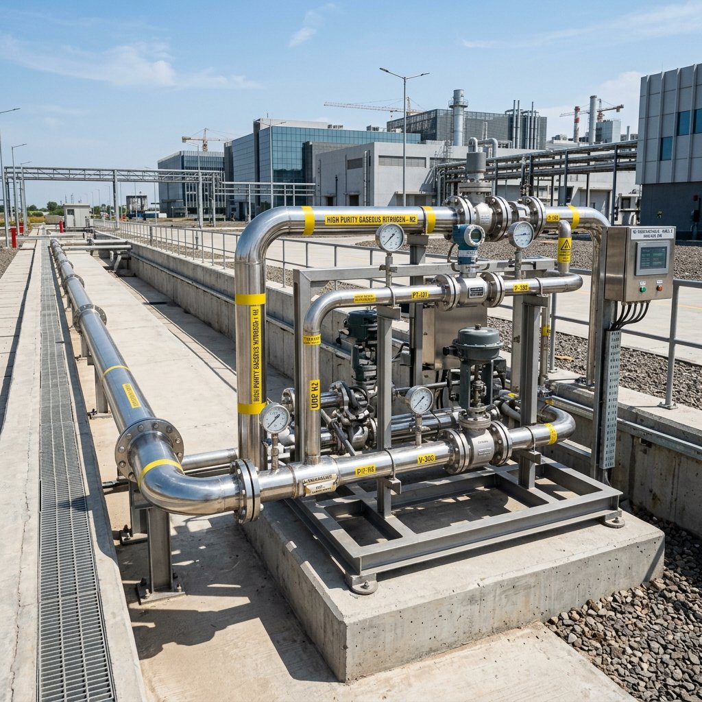

1. Statutory Engineering Codes & Nitrogen Purity Grades
Industrial nitrogen distribution within Dholera SIR is classified into two distinct utility tiers based on consumer end-use:
| Parameter / Specification | Tier 1: General Industrial Grade ($N_2$) | Tier 2: Semiconductor Ultra-High Purity (UHP $N_2$) |
|---|---|---|
| **Applicable Design Standard** | ASME B31.3 / IS 2825 / PESO Codes | SEMI F19, SEMI F20, ASTM G93 Level A |
| **Minimum Gas Purity** | $\ge 99.99\%$ (Industrial Inerting) | $\ge 99.9999\%$ (Grade 6.0 / Cleanroom Fab Spec) |
| **Moisture Content ($H_2O$)** | $\le 5.0\text{ ppm}$ | $\le 1.0\text{ ppb}$ ($T_{dew} \le -100^\circ\text{C}$) |
| **Oxygen Contamination ($O_2$)** | $\le 10.0\text{ ppm}$ | $\le 1.0\text{ ppb}$ |
| **Total Hydrocarbons (THC)** | $\le 1.0\text{ ppm}$ | $\le 0.5\text{ ppb}$ |
| **Carbon Monoxide / Dioxide** | $\le 2.0\text{ ppm}$ | $\le 1.0\text{ ppb}$ |
| **Critical Application in Dholera** | Chemical storage tank blanketing, ETP sparging, mechanical valve actuation | Silicon wafer fabrication, epitaxial growth, load-lock purging, cleanroom fab lines |
2. Pipeline Hydraulic Sizing & Operating Pressures
The high-pressure nitrogen transmission mains route through Dholera’s subterranean concrete multi-utility ducts, physically isolated from high-voltage electrical cable trays and domestic water channels:
| Pipeline Hierarchy / Segment | Nominal Bore (NB) Diameter | Working Pressure ($P_w$) | Design Pressure ($P_d$) | Maximum Gas Velocity ($v_{max}$) |
|---|---|---|---|---|
| **Central Air Separation Unit (ASU) Header** | 200 mm to 300 mm (8″ to 12″) | 16.0 to 25.0 bar | 30.0 bar ($3.0\text{ MPa}$) | $15.0\text{ m/s}$ |
| **Sector Distribution Arterial Mains** | 100 mm to 200 mm (4″ to 8″) | 10.0 to 12.0 bar | 16.0 bar ($1.6\text{ MPa}$) | $12.0\text{ m/s}$ |
| **Plot Terminal Metering Skids** | 50 mm to 100 mm (2″ to 4″) | 8.0 to 10.0 bar | 16.0 bar ($1.6\text{ MPa}$) | $10.0\text{ m/s}$ |
| **Internal Cleanroom Point-of-Use (POU)** | 15 mm to 25 mm (1/2″ to 1″) | 4.0 to 6.0 bar | 10.0 bar ($1.0\text{ MPa}$) | $5.0\text{ m/s}$ (Prevents particle lift-off) |
Pressure Drop & Compressible Gas Flow Formula:
The hydraulic flow behavior across Dholera’s transmission loop is verified using the isothermal compressible gas flow equation under Weymouth/Panhandle formulations:
$$Q = 1.1494 \times 10^{-3} \times \left(\frac{T_b}{P_b}\right) \times \sqrt{\frac{(P_1^2 – P_2^2) \times D^5}{G \times T_{avg} \times L \times Z \times f}}$$
Where: * $Q$ = Volumetric gas delivery capacity at base conditions ($\text{Nm}^3/\text{hr}$). * $P_1, P_2$ = Pipeline inlet and terminal delivery pressures ($\text{kPa absolute}$). * $D$ = Internal pipe diameter ($\text{mm}$). * $L$ = Segment pipeline length ($\text{km}$). * $G$ = Specific gravity of nitrogen relative to air ($0.967$). * $Z$ = Gas compressibility factor ($Z \approx 0.998$ at 12 bar, 25°C). * $f$ = Darcy friction factor for electro-polished stainless steel ($f \approx 0.011$ to $0.013$).
3. Metallurgy, Orbital Welding & Helium Integrity Testing
To guarantee zero outgassing and particle contamination across decadal operational lifespans in Dholera’s coastal environment, strict fabrication protocols are enforced:
“` +———————————————————————————+ | UHP NITROGEN TRANSMISSION SPECIFICATION (DICDL & SEMI STANDARDS) | +———————————————————————————+
| [ Wall Thickness ] Schedule 10S to 40S (ANSI B36.19) |
| [ Core Chemistry ] Cr 16-18%, Ni 10-14%, Mo 2-3%, Carbon <= 0.03% (VIM/VAR) |
| [ Internal Bore ] Electro-polished (EP) Ra <= 0.25 µm (10 µin) Mirror Finish |
| [ Joining ] Automated Orbital Closed-Chamber TIG Welding with Ar Backing |
| [ Leak Rate ] Helium Mass Spectrometer Tested <= 1 x 10^-9 mbar·l/s |
+———————————————————————————+ “`
- Orbital TIG Welding: All pipe joints are fused using automated closed-chamber orbital Tungsten Inert Gas (TIG) welding. Zero filler wire is permitted. The interior bore is purged continuously with 99.9999% argon containing $< 5\text{ ppb } O_2$ to prevent discoloration and heat tinting.
- Helium Leak Detection: Every weld spool undergoes vacuum hood helium mass spectrometry testing under ASTM E498. The acceptable global leak rate is strictly:
- Particulate Cleanliness Verification: Prior to commissioning, lines undergo high-velocity turbulent purging with clean dry nitrogen ($Re \ge 50,000$), followed by laser optical particle counting certifying zero particles $> 0.1\ \mu\text{m}$ per cubic foot of gas.
4. Safety Setbacks, SCADA Instrumentation & Relief Systems
Because nitrogen is an odorless, colorless asphyxiant gas, utility corridors and consumer metering stations incorporate multi-layer fail-safe telemetry:
| Safety System / Instrument | Operational Trigger Threshold | Automated Telemetry & Control Response |
|---|---|---|
| **Ambient Oxygen Sensor ($O_2$)** | Oxygen concentration $< 19.5\%$ | Sounds local visual strobe horns; forces emergency mechanical air exhaust at 12 ACH (air changes/hour). |
| **High Differential Pressure** | $\Delta P > 1.5\text{ bar}$ across filter skids | Transmits maintenance warning to ABCD Command Center; switches stream to parallel standby filter bank. |
| **Pipeline Rupture Sensor** | Pressure rate of drop $\frac{dP}{dt} > 0.5\text{ bar/sec}$ | Automated pneumatic Emergency Shutdown Valves (ESDVs) isolate segment within **$< 3\text{ seconds}$**. |
| **Thermal Relief Valves (TRV)** | Pressure exceeds $110\%$ of design | Discharges vented gas through vertical stacks terminating minimum **3.0 meters above roof eaves**. |
Frequently Asked Questions (FAQ)
Why is SS 316L VIM/VAR steel mandatory for Dholera nitrogen pipelines?
Advanced semiconductor fabrication requires clean gases with zero heavy metal particles and near-zero moisture. SS 316L VIM/VAR (Vacuum Induction Melted / Vacuum Arc Remelted) electro-polished tubing eliminates microscopic surface pores, ensuring an ultra-smooth internal finish (Ra ≤ 0.25 µm) that prevents particle detachment and gas moisture entrapment.What is the standard operating pressure of Dholera’s industrial nitrogen grid?
Sector transmission mains operate at 10.0 to 12.0 bar (145 to 174 psi), while consumer factory gate metering skids regulate delivery down to 8.0 bar. For internal fab cleanroom distribution, point-of-use pressure regulators step down the line to 4.0 to 6.0 bar.How are nitrogen pipeline leaks detected in Dholera SIR?
During commissioning, pipelines undergo Helium Mass Spectrometer leak testing certifying tightness below 1 × 10⁻⁹ mbar·l/s. In live operation, optical oxygen depletion sensors inside utility trenches and automated dP/dt pressure gradient monitoring continuously detect line pressure drops and isolate emergency valves.Can industrial nitrogen lines be laid in open earth trenches in Dholera?
No. Under DICDL master utility corridor guidelines, high-purity industrial gas networks must be installed within the grade-separated utility duct network or mounted on dedicated overhead pipe trestles, fully protected from aggressive saline soil corrosion.What is the maximum allowable gas velocity in semiconductor nitrogen piping?
To eliminate particle generation caused by gas friction and wall shearing, cleanroom Point-of-Use (POU) velocities are capped at 5.0 m/s. Main sector distribution headers maintain maximum velocities between 10.0 m/s and 12.0 m/s.Download Dholera SIR 2026 Investor’s Kit
Get instant access to the official planning documents: Dholera Investment Handbook (PDF), 2026 Land Price List, TP Zone & Village Map, and the NRI Buying Guide.

Join The Discussion