

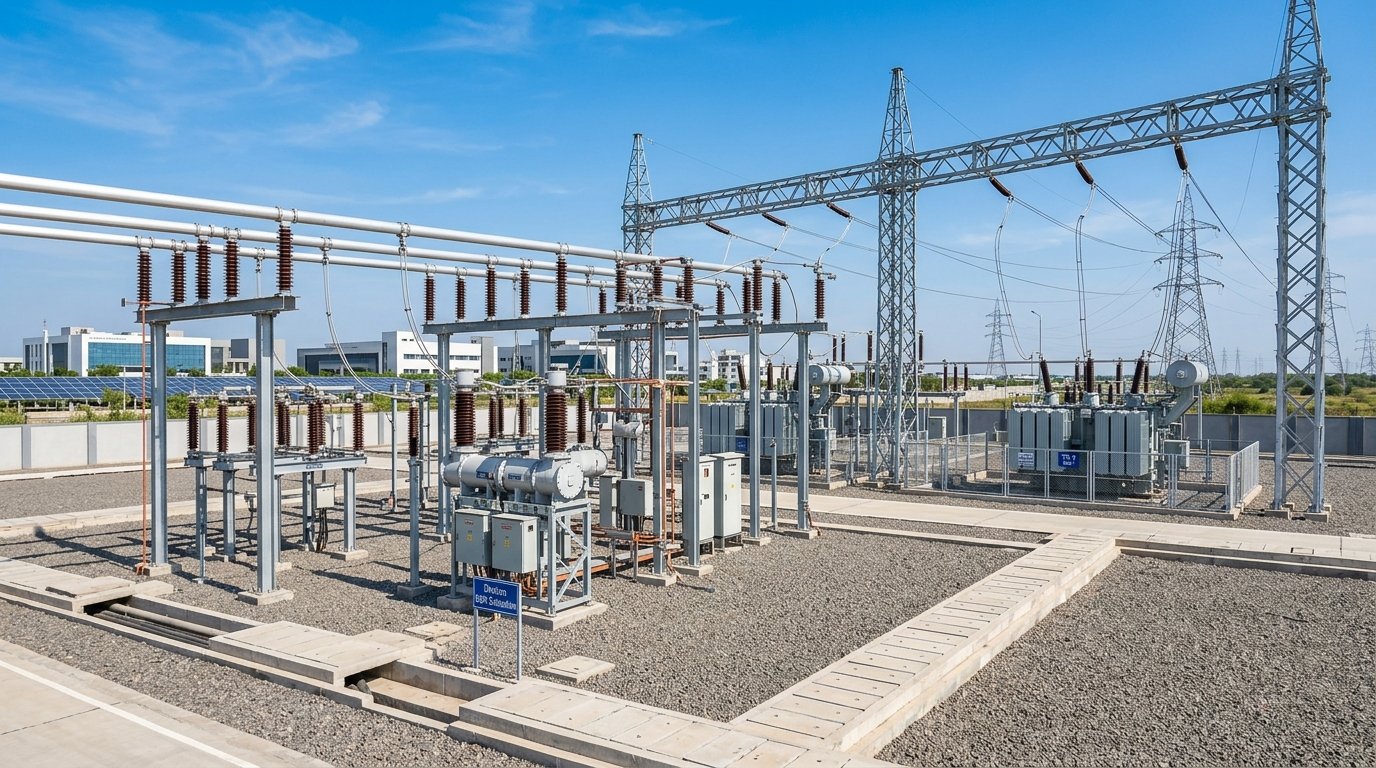
Executive Overview
Bus bars are the backbone of power distribution in Dholera Special Investment Region (DSIR) substations — they collect current from generators or incoming feeders and distribute it to multiple outgoing circuits. Under-sized bus bars overheat, oxidize contact surfaces, and can fail catastrophically under short-circuit conditions. Over-sized bus bars waste material cost and increase switchgear bay dimensions unnecessarily.
Bus bar sizing in Dholera substations is governed by the DSIRDA GDCR 2023 Chapter 9 (Electrical Infrastructure), IS 5082:2008 (copper and aluminium bus bars — specification), IEC 60865-1 (short-circuit current effects in three-phase AC systems), IS 1886 (installation and maintenance of power switchgear), and DICDL (Dholera Industrial City Development Limited) Electrical Infrastructure Manual 2022. This article provides sizing methodology, worked examples, and compliance tables for 11 kV, 33 kV, and 132 kV bus bar applications.
1. Regulatory Framework
| Code / Standard | Scope |
|---|---|
| DSIRDA GDCR 2023 Chapter 9 | Electrical substation infrastructure norms |
| IS 5082:2008 | Copper and aluminium busbars — dimensions and properties |
| IEC 60865-1 | Calculation of short-circuit effects on bus bars |
| IS 1886:2015 | Installation of power switchgear |
| IS 2026 (Power transformer) | Transformer terminal bus bar connections |
| DICDL Electrical Manual 2022 | Dholera zone-specific bus bar specifications |
| CBIP Technical Report 87 | Guidelines for 33 kV/11 kV switchgear |
| CEA Guidelines 2010 | Central Electricity Authority safety regulations |
DSIRDA GDCR 2023 Clause 9.3.1 requires all 11 kV and above bus bar systems in Dholera substations to be designed for a minimum short-circuit withstand duration of 1 second at the rated short-circuit current (Isc) of the system, verified by calculation to IEC 60865-1.
2. Bus Bar Material Properties
| Property | Copper (E-Cu) | Aluminium (EN-AW 1350) | Aluminium Alloy (EN-AW 6101) |
|---|---|---|---|
| Conductivity (% IACS) | 100% | 61% | 55% |
| Current density (max continuous) | 1.6 A/mm² | 1.0 A/mm² | 0.9 A/mm² |
| Tensile strength | 220–250 N/mm² | 60–100 N/mm² | 160–200 N/mm² |
| Density | 8.89 g/cm³ | 2.70 g/cm³ | 2.70 g/cm³ |
| Melting point | 1083 °C | 660 °C | 660 °C |
| Thermal expansion | 17 × 10⁻⁶ /°C | 23 × 10⁻⁶ /°C | 23 × 10⁻⁶ /°C |
| IS 5082 designation | HC-Cu | 1350-H12 | 6101-T6 |
DSIRDA Preference: DICDL Electrical Manual 2022 specifies aluminium alloy EN-AW 6101 (IS 5082) as the preferred bus bar material for 11 kV and 33 kV indoor switchgear in Dholera, due to superior strength-to-weight ratio and resistance to Dholera’s saline atmosphere. Copper is preferred for critical connection points (transformer LV terminals, main incomer contacts).
3. Continuous Current Rating and Sizing
3.1 Current Density Method
The quickest sizing approach uses maximum allowable current density:
$$A_{min} = \frac{I_{rated}}{J_{max}}$$
Where: – A_min = minimum cross-sectional area (mm²) – I_rated = rated continuous current (A) – J_max = maximum current density (A/mm²)
| Material | Indoor Switchgear (J_max) | Outdoor Switchyard (J_max) |
|---|---|---|
| Copper | 1.6 A/mm² | 1.4 A/mm² |
| Aluminium 1350 | 1.0 A/mm² | 0.9 A/mm² |
| Aluminium alloy 6101 | 0.9 A/mm² | 0.8 A/mm² |
Worked Example — 11 kV Indoor Switchgear, 1000 A rated, Aluminium 6101:
$$A_{min} = \frac{1000 \text{ A}}{0.9 \text{ A/mm}^2} = 1111 \text{ mm}^2$$
Select: 2 × 80 mm × 10 mm flat bars (2 × 800 = 1600 mm²) — provides 44% derating margin for thermal contingency.
3.2 Temperature Rise Calculation
Per IS 5082 and IEC 60865:
$$\Delta T = \frac{\rho \cdot I^2}{\lambda \cdot A^2} \cdot \left(\frac{1}{\alpha_{conv} \cdot P_{eff}}\right)$$
Simplified for engineering use — maximum permissible temperature rise:
| Operating Environment | Max Conductor Temp | Max Rise Above 40 °C Ambient |
|---|---|---|
| Indoor switchgear (IS 1886) | 90 °C | 50 °C |
| Outdoor bus (IS 1886) | 80 °C | 40 °C |
| Contact surfaces | 75 °C | 35 °C |
| Insulated bus duct | 105 °C | 65 °C |
4. Standard Bus Bar Sections (IS 5082)
4.1 Flat Bus Bar Standard Sections
| Width × Thickness (mm) | CSA (mm²) | Current (Copper, A) | Current (Al 6101, A) |
|---|---|---|---|
| 25 × 5 | 125 | 200 | 112 |
| 40 × 5 | 200 | 320 | 180 |
| 50 × 6 | 300 | 480 | 270 |
| 63 × 8 | 504 | 806 | 453 |
| 80 × 10 | 800 | 1280 | 720 |
| 100 × 10 | 1000 | 1600 | 900 |
| 125 × 10 | 1250 | 2000 | 1125 |
| 160 × 12 | 1920 | 3072 | 1728 |
(Current values at J_max for single flat bar, horizontal on edge, 40 °C ambient)
4.2 Multiple Parallel Bars (Derating)
For multiple flat bars in parallel (to achieve higher current ratings):
| Number of Parallel Bars | Derating Factor |
|---|---|
| 2 bars | 0.90 |
| 3 bars | 0.80 |
| 4 bars | 0.73 |
Minimum gap between parallel bars: 10 mm (or bar thickness, whichever is greater) for natural convection cooling — DSIRDA GDCR Clause 9.3.5.
5. Short-Circuit Withstand Rating
5.1 Thermal Short-Circuit Current (Ith)
Per IEC 60865-1:
$$A_{SC} = \frac{I_{SC} \times \sqrt{t_{SC}}}{K}$$
Where: – A_SC = minimum CSA for short-circuit withstand (mm²) – I_SC = short-circuit current (kA rms) – t_SC = short-circuit duration (seconds) — DSIRDA minimum 1.0 s – K = material factor (for copper: 143; for aluminium: 94)
Worked Example — 33 kV Bus, I_SC = 25 kA, t_SC = 1.0 s, Aluminium 6101:
$$A_{SC} = \frac{25000 \times \sqrt{1.0}}{94} = 265.9 \text{ mm}^2$$
Select minimum 300 mm² aluminium section. Final selection governed by whichever is larger: continuous rating or short-circuit rating.
5.2 Electromagnetic Force on Bus Bars (Mechanical Rating)
Short-circuit currents produce electromagnetic forces between parallel conductors:
$$F = \frac{2 \times 10^{-7} \times I_{peak}^2 \times L}{d}$$
Where: – F = force per unit length (N/m) – I_peak = peak short-circuit current (A) = I_SC × 2.55 (for X/R = 10) – L = span between supports (m) – d = centre-to-centre distance between conductors (m)
DSIRDA requires bus bar supports to be spaced at ≤ 1.0 m centres for 11 kV indoor switchgear and ≤ 1.5 m for 33 kV outdoor switchyard, with support insulators rated to withstand calculated electromagnetic force × safety factor 2.5.
6. Bus Bar Design for Dholera’s Three Voltage Levels
| Voltage Level | Typical Continuous Rating | Isc Rating | Standard Bus Section | Material |
|---|---|---|---|---|
| 11 kV indoor LV room | 630–1250 A | 25 kA / 1 s | 2 × 80 × 10 mm | Al 6101 |
| 11 kV indoor 11 kV panel | 1250–3150 A | 40 kA / 1 s | 3 × 100 × 10 mm | Al 6101 |
| 33 kV outdoor switchyard | 630–1250 A | 25 kA / 1 s | 80 × 10 mm (single) | Al 6101 |
| 33 kV outdoor switchyard | 1600–3150 A | 31.5 kA / 1 s | 2 × 125 × 12 mm | Al 6101 |
| 132 kV switchyard | 1250–2000 A | 40 kA / 1 s | ACSR/AAAC stranded conductor | Aluminium |
7. Bus Bar Installation Requirements (DSIRDA GDCR Clause 9.3)
“` TYPICAL 11 kV BUS BAR ARRANGEMENT (INDOOR)
Incoming Bus Section Outgoing Feeders ┌──────────────────────────────────────┐ │ R ═══════════════════════════════ │ ← 3-phase flat bus, R-Y-B │ Y ═══════════════════════════════ │ mounted on edge, 200 mm centres │ B ═══════════════════════════════ │ │ ↑ Support insulator 1.0 m max │ └──────────────────────────────────────┘ Aluminium 2 × 80 × 10 mm per phase Min phase-to-phase clearance: 100 mm (11 kV) “`
| Parameter | 11 kV Indoor | 33 kV Outdoor |
|---|---|---|
| Phase-to-phase clearance | 100 mm | 320 mm |
| Phase-to-earth clearance | 75 mm | 250 mm |
| Support insulator spacing | ≤ 1.0 m | ≤ 1.5 m |
| Bus bar mounting | On edge (horizontal) | On edge or tube |
| Joint overlap | ≥ 2 × bar width | ≥ 2 × bar width |
| Joint bolt torque | Per manufacturer — verified with torque wrench | Same |
| Expansion joint | Every 10 m (Al) or 15 m (Cu) of run | Every 8 m (Al) |
8. Surface Treatment and Jointing
| Joint Type | Treatment | Standard |
|---|---|---|
| Aluminium-aluminium | Oxide removal by wire brush + contact compound | IS 8084 |
| Aluminium-copper | Bimetallic connector (Al-Cu clad) | IS 5082 |
| Copper-copper | Oxide removal, tin-plated surface | IS 613 |
| All joints | Silver/tin-plated contact surface area | CBIP TR 87 |
Bolted joint torque: Per manufacturer’s table — typically M10 bolt: 20–25 N·m; M12: 35–40 N·m; M16: 60–70 N·m. Use calibrated torque wrench — mandatory per DSIRDA GDCR Clause 9.3.8.
FAQ
What is the maximum current density for aluminium bus bars in Dholera industrial substations?
Per IS 5082:2008 and DSIRDA GDCR 2023, the maximum continuous current density for aluminium alloy EN-AW 6101 bus bars is **0.9 A/mm²** for indoor switchgear and **0.8 A/mm²** for outdoor switchyard applications, assuming 40 °C ambient temperature and natural air cooling.What is the minimum short-circuit withstand duration for bus bars in Dholera substations?
DSIRDA GDCR 2023 Clause 9.3.1 mandates a minimum **1 second** short-circuit withstand at the rated Isc current. The minimum bus bar cross-section for short-circuit withstand is calculated per IEC 60865-1 using the formula: A_SC = (I_SC × √t) / K, where K = 94 for aluminium.Why is aluminium alloy preferred over pure aluminium for bus bars in Dholera?
DICDL Electrical Manual 2022 specifies aluminium alloy EN-AW 6101 (IS 5082) over pure aluminium (1350 series) for Dholera because 6101 alloy has significantly higher tensile strength (160–200 N/mm² vs. 60–100 N/mm²), which is essential to resist the mechanical forces generated during short-circuit events in Dholera’s high fault-current infrastructure.How far apart must bus bar supports be placed in an 11 kV indoor switchgear room in Dholera?
DSIRDA GDCR 2023 Clause 9.3.5 requires bus bar supports at a maximum spacing of **1.0 m centres** for 11 kV indoor switchgear. Support insulators must be rated to withstand the calculated electromagnetic short-circuit force multiplied by a safety factor of 2.5.What surface treatment is required for aluminium bus bar joints in Dholera?
All aluminium bus bar joints require removal of the oxide layer by wire brushing immediately before jointing, followed by application of an anti-oxidant joint compound (IS 8084). Aluminium-to-copper joints must use bimetallic (Al-Cu clad) connectors. All contact surfaces should be silver or tin-plated. Bolt torque must be applied using a calibrated torque wrench per DSIRDA GDCR Clause 9.3.8.Download Dholera SIR 2026 Investor’s Kit
Get instant access to the official planning documents: Dholera Investment Handbook (PDF), 2026 Land Price List, TP Zone & Village Map, and the NRI Buying Guide.

Join The Discussion